by CM Cooper · Cited by 8 — DIGITAL SIMULATION OF “BRASSINESS” AND AMPLITUDE-. DEPENDENT PROPAGATION SPEED IN WIND INSTRUMENTS. Charles M. Cooper and
182 KB – 6 Pages
PAGE – 1 ============
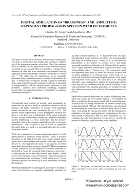
Proc. of the 13 th Int. Conference on Digital Audio Effects (DAFx -10), Graz, Austria, September 6 -10, 2010 DAFX -1 DIGITAL SIMULATION OF ÒBRASSINESSÓ AND AMPLITUDE -DEPENDENT PROPAGATION SPEED IN WIND INSTRUMENTS TEMPLATES FOR DAFX-08, FINLAND, FRANCE Charles M. Cooper and Jonathan S. Abel Center for Computer Research In Music and Acoustics (CCRMA) Stanford University Stanford, CA 94305 USA [ccooper | abel]@ccrma.stanford.edu ABSTRACT The speed of sound in air increases with pressure, causing pre s-sure peaks to travel faster than troughs, and leading to a sharpe n-ing of the propagating pressure waveform. Here, this no nlinear effect is explored, and its application to brass instrument synth e-sis and its use as an audio effect are described. Acoustic mea s-urements on tubes and brass instruments are presented showing significant spectral enrichment, sometimes referred to a s Òbrass i-ness.Ó The effect may be implemented as an amplitude -dependent delay, distributed across a cascade of incremental d e-lays. A bidirectional waveguide, having a pressure -dependent delay, appropriate for musical instrument synthesis, is presented. A computationally efficient lumped -element processor is also presented. Example brass instrument recordings, originally played softly, are spectrally enriched or ÒbrassifiedÓ to simulate a fortissimo pla ying level. 1. INTRODUCTION Conventional linear analys is of acoustic wave propagation a s-sumes that the speed of sound is essentially co nstant in the air medium, and digital simulations of musical wind instruments usually incorporate the same assumption [1, pp. 11 -12]. The mem ory buffer representing a linear propagation medium pr o-duces a time delay that is inde pendent of the signal amplitude. Of the various non linearities producing amplitude -dependent spectral brighte ning in a brass instrument, only the pressure -controlled valve in the exc itation and feed back path is commonly implemented. One exception is [2], in which an a mplitude -dependent delay was used in a waveguide algorithm for synth e-sizing brass sounds. While the assumption of co nstant propagation speed is a valid approximation at moderate sound pres sure lev els , it becomes unrealistic at the high levels that occur inside musical instr u-ments such as the tro mbone and trumpet, which can exceed 160 dB [3, 4] . The high -pressure peaks of an acoustic wav eform travel faster than the low -pressure troughs [5] . The se propag ation velocity differences lead to progressive wav eform distortion (as illustrated in Figure 1), increasing high -frequency con tent and Ñat high pressure levels and long acous tic path lengths Ñ shock waves with impulsive pressure transitions. Musical acou sticians have doc umented the occurrence of both shock waves [4] and sub -shock spectral enrichment [6] in brass instruments, i ncluding the trombone. Amplitude -dependent wave propagation speed can be modeled in terms of the acoustic wave equation , and digitally simulated u s-ing finite element methods [7]. As developed below, the pre s-sure -dependent sound speed has the effect of a level -dependent time delay on traveling waves . Tassart, et al. [8 ] described this phenomenon in the context of acoustic waves and digital waveguide simulat ions. Valimaki, et al. [9 ] described the applic a-tion of signal -dependent no nlinearities to physical models using fractional -delay filters. Tolonen, et al. [10 ] proposed an ampl i-tude -dependent time delay to model the inc rease in pitch with waveform amplitude on a vibrating string. In this work, we e x-plore both distributed and lumped implementations of an ampl i-tude -dependent sound speed. The focus here is on Òphysically informedÓ sonic mode ling [11 ], suitable for digital a udio effects, rather than precise conformity with the acoustical physics of m u-sical instruments. The resulting algorithms are sui table for real -time digital processing with relatively low computational co m-plexity. Signal delays varied at audio rates are c apable of producing spe c-trally rich sou nds. In one example, Stilson [12 ] modulated the delay in a Karplus -Strong string model with a sinusoid having a frequency near the string fundamental. In another e xample [13 ], sounds having both FM and AM chara cteris tics were generated by modulating the coefficients of spe ctral delay filters at audio rates. Associating the varying time delay with the i nstantaneous amplitude of an input signal produces a brightening of the spe c-trum similar in character to that of a b rass instrument [3]. A c-cordingly, the term Òbra ssificationÓ is used here to describe the process of delaying a signal according to its ampl itude. !”!!#!!$!!%!!&!!’!!(!!)!!*!!”!!!!”!”+,-./0123!”!!#!!$!!%!!&!!’!!(!!)!!*!!”!!!!”!”+,-./0123!”!!#!!$!!%!!&!!’!!(!!)!!*!!”!!!!”!”+,-./0123 Figure 1: Waveforms of sinusoidal pressure wave s at low, me-dium and high pressure levels, after propagat ing the same di s-tance.
PAGE – 2 ============
Proc. of the 13 th Int. Conference on Digital Audio Effects (DAFx -10), Graz, Austria, September 6 -10, 2010 DAFX -2 In Section 2 below, the nonlinear wave equation incorporating a pressure -dependent sound speed is explored, and acoustic mea s-urements showing waveform sharpening are presented. Section 3 discusses discretization of the nonlinear wav e equation. Impl e-mentations of bidirectional waveguide sections producing an a m-plitude -dependent propagation time and aimed at brass instr u-ment synthesis applications are described in section 4. Audio effects architectures employing an amplitude -dependen t delay, and including equalized and side -chain structures, are pr esented in Section 5. Finally, Section 6 concludes the paper. 2. AMPLITUDE -DEPENDENT WAVE PROPA GATION 2.1. Acoustic Wave Propagation and Waveform Sharpening The one -dimensional acoustic wave equat ion describes the b e-havior of air pressure fluctuations p(x, t) along position x and time t, ! “2p”t2=v2x,t()”2p”x2 (1) where v(x, t) represents the speed of sound [ 5]. The wave equ a-tion (1) propagates disturbances along the x axis with speed v(x,t ), which depends weakly on the local, instantaneous air pre s-sure, ! v(x,t)=c0+”p(x,t)P0 (2) where c0 represents the small -signal speed of sound in air, P0 the undisturbed air pressur e, and ! the coefficient of nonlin earity. The quantity !/P0 is positive, causing sound wave peaks to travel faster than troughs. This effect progressively distorts the prop a-gating waveform, as illustrated in Figure 1, sharpening the trans i-tions between successive low -pressu re and high -pressure po r-tions of the waveform . A sound that starts off as a sinusoid will acquire more of a sawtooth shape, and an i ncreasing amount of high -frequency content. If the product of the sound amplitude and the distance traveled becomes sufficiently large, the slower moving trough would seem ingly be overtaken by the prece ding peak. W hat in fact happens, however, is that a shock forms Ñan abrupt, nearly instantan eous, transition between trough and peak. Figure 2: Multivalued (non -physical) spatial waveform at a fix ed time that would seemingly result from a peak overtaking a trough. Instead, a shock transition is formed. From [5], p. 104. The shock ap pears near the location at which the areas of the fast -propagating p eak ahead of the shock and the slow -propaga ting t rough behind the shock are balanced; this point is marked by x sh in the example of Figure 2 . It turns out that loss mechanisms in air, not included in equation (1), lead to the diss i-pation of a shock wave after its for mation [5]. As an example of the mag nitudes involved, consider a sound of 140 dB SPL, which is intense but well below the maximum le v-els measured in musical instruments such as the trombone [4,6]. This level corresponds to a peak -to-peak pressure fluctuation of 679 Pa, which is nearly 0.7 p ercent of the static atmospheric pressure of 10 5 Pa. In equation (2), the physical quantity ! for air is a pproximately 1.2 times the nominal speed of sound, so the difference in speed between the peaks and the troughs of the waveform is approx imately 0.81 4 percent of the average or small -signal speed. Over a propagation distance of 2 m (typical for the tro mbone), this speed difference between peak and trough leads to an arrival -time difference of 48.7 microseconds, which is approx imately one -fourth of the period of a 5 kHz signal. This corr esponds to a significant steepening of the waveform and brighte ning of the spectrum. 2.2 Acoustic Measurements To confirm and quantify the occurrence of an amplitude -dependent propagation velocity at sound levels and path lengths corresponding to those inside a trumpet or trombone, we a ttached a compression -drive r loudspeaker (Atlas PD -30, 30 W) to a PVC plastic tube with inside diameter of 1.27 cm and length 3 m. A microphone was placed inside the tube 2 m from the source, a distance roughly corr esponding to the acoustic path length of a trombone. Wi ndowed bursts of several cycles of a 2.205 kHz sine wave were applied to the loudspeaker using a range of a m-plitudes. The received micr ophone signals, seen in Figure 3 (a), and normalized to have unit amplitude in Figure 3 (b), show no-ticeable waveform shar pening, with their peaks traveling faster than their troughs in a manner well approximated by equation (2). The propagating wave forms expe rience a high -frequency enrich ment, even at signal le vels and path distances well below those required for shock formation. !!”#!”$!”%!”&!”‘!”(!”)!!”&!!”$!!”$!”&*+,-.+/.,+00+1-23/415,60+784-!!”#!”$!”%!”&!”‘!”(!”)!#!!”‘!!”‘##”‘*+,-.+/.,+00+1-23/415,60+784- Figure 3 : Acoustic waveforms of windowed sinuso idal bursts at three differe nt pressure levels (top) and the same signals norma l-ized to the same level and sligh tly offset vert ically for clarity (bottom).
PAGE – 3 ============
Proc. of the 13 th Int. Conference on Digital Audio Effects (DAFx -10), Graz, Austria, September 6 -10, 2010 DAFX -3 3. WAVE PROPAGATION SIMULATION 3.1 Wave Equation Discretization While the wave equation (1) provides a general description of the behavior of the disturbances propagating in the medium, we will find it usef ul to separately consider left – and right -traveling waves, governed by the first -order equation pair ! “p”t±(c0+#pP0)”p”x=0 . (3) Given a pressure g(x), defined along the x axis at time t=0, and a wave propagating in the +x direction ! p(x,t)=gx”(c0+#p(x,t)P0)t$ % & ‘ ( ) . (4) Assuming !=0, corresponding to an ideal linear medium, the in i-tial waveform g(x) is seen to travel down the x axis with speed c0. After a time !t, the waveform is simply translated , intact, a di s-tance c0 !t. By contrast, if ! is positive, as it is for an air m e-dium, the wav eform evolves as it propagates: the peaks travel faster than the troughs. For a pressure h(t), defined for all time at the position x=0, the pressure propagating along the +x axis satisfie s ! p(x,t)=ht”xc0+#p(x,t)P0$ % & & & & ‘ ( ) ) ) ) . (5) For !=0, the pressure noted at x0>0 is simply the pressure at x=0, delayed by x0/c0. In the presence of !>0, the pressure at x0 is a p-proximately the pressure amplitude at x=0, delayed accor ding to its value , with peaks arriving relatively sooner than troughs. The fact that the nonlinear wave equation implies a pressure -dependent time delay can be seen via a simple discretization of (4). Co nsider a delay line having sample locations labeled by n, and co ntai ning a pressure waveform p(n,t ) at time t. Assume that the small -signal sound speed c0 is one sample location per sa m-ple interval, and approximate the time and position d erivatives by first -order differences, ! “p”t=p(n,t)#p(n,t#1), (6) ! “p”x=p(n,t#1)#p(n#1,t#1) . (7) A little algebra gives the delay line waveform at time step t in terms of its contents at time step t-1, ! p(n,t)=”p(n,t#1)+(1#”)p(n#1,t#1) (8) where ! “=#$pP0 . (9) Note that when !=0, correspondin g to propagation in a linear medium, the waveform is simply shifted intact, one sample pos i-tion for each new time step. In general, when ! is not equal to zero, the waveform at time t and position n is a linear interpol a-tion of the wav eform at positions n and n-1 at time t-1. The waveform at time t and position n, ther efore, approximates the waveform at time t-1 in the neighborhood of location n-1, just before n-1 for positive pressures and just a fter n-1 for negative pressures. A similar discretization gives the pressure at position n as a linear interpolation of its value at position n-1 between times t and t-1, ! p(n,t)=”p(n#1,t)+(1#”)p(n#1,t#1) (10) where the interpolation coefficient ” is ! “=#$pP01+$pP0 . (11 ) We again have the interpretation that the pressure at position n is the pressure at position n-1 delayed according to its value. 3.2 Amplitude -Dependent Delay In view of the interpretation above, the amplitude -dependent propagation may be implemented in d iscrete time as a ca scade of amplitude -dependent elements as shown in Figure 4. A buffer indexed by n contains the propagating waveform. At every time step t, the waveform at position n is replaced by its value at pos i-tion ! n”1″#pP0 , (12) where a sound speed of c0 = 1 sample position per sample inte r-val is assumed. Figure 4: Discretized unidirectional amplitude -dependent time delay using cascaded elements. The arrows entering the top of each elem ent represent the modulation of the elementÕs delay by the pressure at its input. The amplitude -dependent delay elements comprising the cascade in Figure 4 may be implemented in a number of ways [14, 15 ]. FIR approaches are pa rticularly simple: The inp ut is upsampled, and a low -order interpolation applied. Linear interpolation a c-cording to (8) or (10 ), or fourth -order Lagrange interpolation works well with modest upsampling fa ctors such as two or four. The high -frequency droop present in the FIR inter polation is not unwelcome, as it is in some sense similar to damping mech a-
PAGE – 4 ============
Proc. of the 13 th Int. Conference on Digital Audio Effects (DAFx -10), Graz, Austria, September 6 -10, 2010 DAFX -4 nisms present in air, not included in (3), which affect the form a-tion and evol ution of shock. First -order allpass filtering may also be used to implement the needed variable delay. There are, however, some drawbacks to this approach. First, these filters are dispersive, such that when the low frequencies are delayed a little more than one sa mple, the high frequencies will be delayed a little less than one sample. Second, distortio n artifacts may be intr oduced by audio rate modulation of allpass coefficients, although this too can be co n-trolled to some extent [13, 16 ]. Both the underlying mathematics and the available implement ation options are generally analogous to those describe d in [10] for modeling tension -dependent no n-lineari ty in plucked strings. Overall, we suggest using upsa m-pling with a low -order FIR interpolator to implement the desired amplitude -dependent delay element. 4. MUSICAL INSTRUMENT SOUND SYNTHESIS 4.1 Bid irectional waveguide The discretization above may be configured to implement a bi -directional waveguide and used to sim ulate the bore of a wind instrument. To do so, two variable delay lines propagating si g-nals in opposite directions are used. In an ins trument bore, ho w-ever, the sound speed depends on the total bore pressure, rather than the individual left – and right -traveling pressures. The su g-gested waveguide i mplementation is shown in Figure 5 . At every position along the bi directional waveguide, t he sum of the left – and right -going press ures is used to modulate the respective var i-able delays. Figure 5: Modeling bidirectional wave propagation with ampl i-tude -dependent delay elements 4.2 Lumped -element Simplification The complexity of the w aveg uide shown in Figure 5 may be r e-duced by approxim ating the effect of a number n of cascaded variable delays into a single combined variable delay of value n times (1 +!p/P 0). Using lumped delay elements, the left – and right -going waves can be summed at a s parse set of locations along the acoustic tube to provide a delay control signal that i n-cludes the effect of the interaction between t he outgoing and r e-flected waves. Only a limited number of delay locations are r e-quired, because the pressure wave inside t he bore of a brass i n-strument is dominated by low frequencies [6], corresponding to low spatial frequencies. Alternatively, a uni directional impl e-mentation of the variable delays may be co nsidered sufficient , in view of the fact that the high -frequency sig nal components , which are the ones primarily affected by delay -time modulation, are largely transmitted through the in strument bell rather than being r eflected back into the bore. On the other hand, in detailed digital simulation of the trombone for synth esis appplications [17 ], it was shown that including the backward wave within the oscillatory feedback loop does affect the fund amental frequency and increase the brassiness of the synth esized output signal. Figure 6: Commuting a single large amplitud e-dependent delay to the end of a fixed d elay. 5. AUDIO EFFECTS 5.1 Lumped ÒBrassificationÓ In the context of applying amplitude -dependent delay to existing audio signals (rather than de novo synthesis of musical sounds), there is little reason to m odel the detailed physics by implemen t-ing distributed variable delays. A natural approach is to lump the delay processing into a single ampl itude -dependent delay lin e, as shown in Figure 6. Each new arriving signal sam ple, after u p-sampling to a higher rat e, can be written (added) into the appr o-priate positions in the delay line using linear (or Lagrange) inte r-polation. To scrupulously model the physics of acoustic wave propagation , including shock fronts at high amplitudes, any samples that are computed t o be overtaken by earlier higher -amplitude samples should be di scarded, as described in Section 2.1 . This logic can be impl emented in the interpolated delay line. We have found experime ntally, ho wever, that omitting th is feature (and instead interpolatin g and adding every input sample into the d elay line even if it arrives ÒlateÓ) results in processed sounds with a brighter spe ctrum that, i n the opinion of the authors, sounds more musically appealing. This may be attributable to the fact that acoustic s hock waves corr espond to energy loss, and that a larger amount of time -delay mod ulati on can be applied to the signal when the shock -wave feature is omi tted . When the shock -wave feature is omitted from the delay -line i m-plementation, the amplitude -dependent time -delay becomes equivalent to phase or frequency mod ulation (PM or FM). The high -frequency harmonics of a wind instr ument sound may be regarded as ÒcarrierÓ si gnals that are phase -modulated by the dominant low -frequency pressure wave inside the bore o f the i n-strument. Phase modulation of a single carrier frequency pr o-
PAGE – 5 ============
Proc. of the 13 th Int. Conference on Digital Audio Effects (DAFx -10), Graz, Austria, September 6 -10, 2010 DAFX -5 duces sidebands that ge nerally increase in prominence as the phase excursion increases, but the rel ationship is not monotonic. Instead, according to standa rd PM and FM theory [18 ], the am-plitude of each generated sideband is proportional to an oscill a-tory Bessel function, resulting in a complex, smooth and mus i-cally appealing variation in the spectrum. It is perhaps signif i-cant that FM synthe sizers are considered particularly succes sful when emulating brass i nstruments. 5.2 Audio Effects Architectures Since the acoustic signal inside the bore of a musical instrument consists primarily of low frequencies [6] , especially the fund amental, it is appropriate to filter the signal so as to emphasize its low -frequency content. In this way, the digitally simulated pre ssure waveform for modulating the time delay will correspond more closely to that inside the instrument. After the amplitude -dependent propaga tion delay is applied, this filter ing should be compensated by a complementary filter emphasizing high fr equencies and corresponding , for instance, to the frequency -selective transmi ssion through the flared bel l of the horn. Figure 7 : Equalized ÒbrassifierÓ with conditioning filter before the amplitude -dependent delay and equalization filter after it. This architecture Ñan equalized ÒbrassifierÓ Ñis shown in Figure 7. The filter c(z) conditions the signal to emphasize those fe a-tures of the signal important for contro lling the brassifi cation. The filter q(z) provides complementary equalization chosen to be the in verse of c(z). With conditioning and equalization filters arranged in this manner, low -amplitude signals will pass through the process u nchanged, while high -amplitude signals will be brassified (spe ctrally brightened). Another brassifier architecture provides a side -chain signal for con trolling the delay modification, analogous to the generalized time -varying fractio nal delay used in [10 ] to model string tension modulation. As shown in Figure 8 , a filtered version of an i nput sig nal is used to control the amplitude -dependent delay exper i-enced by the i nput. This structure, when used with a low -pass side -chain filter, improves the output signal quality of the brass i-fier while retaining the desired spectral enrichment. Unlike the signal -dependent allpass t echnique of Kleimola, et al. [13], the use here of upsampling and linear or Lagrange inte rpolation permits very large amounts of side -chain modulation to be a p-plied without c ausing exce ssive aliasing or other undesired di s-tortion. Figure 8: ÒBrassifierÓ with side chain for modulation s ignal. The filter c(z) conditions the input signal, typically by emphasi z-ing low frequencies, to produce a signal suitable for modulating !, the amplitude -dependent time delay. An example of the spectra resulting from using the side -chain architecture to process a recor ded trumpet signal is shown in Figure 9 . The sound files corresponding to these spectra and r e-lated examples are available on the World Wide Web [19 ]. !”!!!#!!!$!!!%!!!&!!!!!”!!”!#!$!'()*+),-./0,/12345607+8)/0,/89!”!!!#!!!$!!!%!!!&!!!!!”!!”!#!$!'()*+),-./0,/12345607+8)/0,/89 Figure 9 : Spectrum of unmod ified trumpet signal (top) and the pro cessed or ÒbrassifiedÓ spectrum (bottom) . 6. CONCLUSIONS AND FUTURE WORK Amplitude -dependent digital signal delay, derived from concepts of nonlinear acou stics, has been shown to produce spe ctra and sounds that are brass -like in character. The technique can be used for synthesis of musical instrument sounds in physical mo d-els, but as implemented here it is especially suitable for modific a-tion of pre -record ed or live instrument sounds as a dig ital audio effect. The digital implementation is capable of modeling the production of acoustic shock waves at high signal amplitudes, but substantial or even increased ÒbrassinessÓ can be achieved by eliminating shoc k-wave emulation (i.e., the discarding of late -arriving samples) and using a larger amplitude -dependent delay and modulation index. When shock produ ction is eliminated, the effect can best be interpreted and analyzed in terms of phase or frequency modul ation. The suggested implementation Ñas a single lumped delay line with FIR interpolation Ñis free of unwanted artifacts such as spectral dispersion, and its low computational complexity is sui t-able for real -time applications. As a digital audio effect or for
PAGE – 6 ============
Proc. of the 13 th Int. Conference on Digital Audio Effects (DAFx -10), Graz, Austria, September 6 -10, 2010 DAFX -6 sample -based synthesis, the technique can be used to enrich the spectrum and modify the a pparent dynamic level of a musical instrument sound. The effectiveness of amplitude -dependent d e-lay in producing or enhancing brassiness suggests that this no n-linear effect is desirable as a fundamental component of physical models for sy nthesizing brass instrument sounds. Future work will include the application of this technique to non -brass instr ument sounds. Another anticipated extension is the use of multi -band processing so that a modulation index large enough to produce audibly significant PM sidebands can be a p-plied even to low -frequency signal components. 7. ACKNOWLEDGMENTS Charles Cooper would like to thank Jonathan Abel and Julius Smith for serving as his faculty sponsor s as a Visiting Researcher at the Center for Computer Research and Musical Acoustics at Stanford Unive rsity. 8. REFERENCES [1] J. Smith, Physical Audio Signal Processing , W3K Publis h-ing, 2007. [2] X. Rodet and C. Vergez, ÒNew algorithm for nonlinear propagation of a sound wave, Application to a physical model of a tru mpet,Ó Journal of Signal Processing, Vol. 4, No. 1, pp. 79 -87, January 2000 . [3] J. Gilbert, L. Menguy, and M. Campbell, ÒA simulation tool for brassiness studies,Ó J. Acoust. Soc . Am., Vol. 123, No. 4, April 2008. [4] A. Hirschberg, J. Gilbert, R. Msallam, and A. Wijnands, ÒShock waves in trombones,Ó J. Acoust. Soc. Am., Vol. 99, No. 3, March 1996, p. 1758. [5] M. Hamilton and D. Blackstock, Nonlinear Acoustics, Acoustical Society of Amer ica, 2008. [6] P. Rendon, F. Orduna -Bustamante, D. Narezo, and A. Perez -Lopez, ÒNonlinear progressive waves in a slide tro m-bone resonator,Ó J. Acoust. S oc. Am., Vol. 127, No. 2, Fe b-ruary, 2010. [7] S. Bilbao, Numerical Sound Synthesis, John Wiley & Sons, Ltd., 20 09. [8] S. Tassart, P. Depalle, S. Dequidt, ÒA fractional delay a p-plication: time -varying propagation speed in waveguides,Ó Proceedings of the International Computer Music Confe r-ence, pp. 256 -259, Thessaloniki, Greece, 1997. [9] V. Valimaki, T. Tolonen , and M. Karjalainen , “Signal -Dependent Nonlinearities for Physical Models Using Time -Varying Fractional Delay Filters,” in Proceedings of the I n-ternational Computer Music Conference (ICMC98) , pp. 264-267, Ann A rbor, Michigan, USA, October 1 -6, 1998. [10] T. Tolonen, V. Valimaki, and M. Karjalainen, ÒModeling of tension modulation nonlinearity in plucked strings,Ó IEEE Transactions on Speech and Audio Processing , Vol. 8, No. 3, 2000 . [11] P. Cook, Real Sound Synthesis for Interactive Applic ations, A.K. Peters, 2002 . [12] T. St ilso n, ÒGeneral weirdness with the K arplus -Strong string,Ó presented at the 1995 International Computer M u-sic Conference, avai lable at https://ccrma.stanford.edu/~stilti/papers/we irdstring.ps.gz , Accessed April 5, 2010. [13] J. Kleimola, J. Pekonen, H. Penttinen, V. Valimaki, and J. Abel, ÒSound synthesis using an allpass filter chain with audio -rate coefficient modulation,Ó Proc. of the 12th Int. Confe rence on Digital Audio Effects (D AFx-09), 2009. [14] V. Valimaki and T. Laakso, ÒPrinciples of fractional delay filters,Ó IEEE International Conference on Acoustics, Speech, and Signal Processing (ICASSP Õ00), June, 2000. [15] T. Laakso, V. Valimaki, M. Karjalainen, and U. Laine, ÒSplitting the uni t delay – Tools for fractional delay filter design ,Ó IEEE Signal Processing Magazine, vol. 13, no. 1, pp. 30-60, Jan. 1996. [16] V. Valimaki and T. Laakso , Ò Suppression of transients in variable recursive digital filters with a novel and efficient cancellation method ,Ó IEEE Transactions on Signal Pro c-essing , vol. 46, no. 12, pp. 3408 -3414, Dec. 1998 . [17] R. Msallam, S. Dequidt, R. Causse, and S. Tassart, “Phys i-cal Model of the Trombone Including Nonlinear Effects. Application to the Sound Synthesis of Loud Tones,” Acta Acustica united with Acustica , Volume 86, Number 4, July/August 2000, pp. 725 -736. [18] J. Chowning, ÒThe synthesis of complex audio spectra by means of frequency modulation,Ó Journal of the Audio E n-gineering Society, Vol. 21, No. 7, pp. 526 -534, 1973. [19] C. C ooper, J. Abel, ÒBrassification Sound Examples,Ó avai l-able online at http://ccrma.stanford.edu/~ccooper/DAFx2010/examples.
182 KB – 6 Pages