by B XIA · 2015 · Cited by 1 — Key words: Numerical Simulation; Centrifugal Classification; Cut Size. Abstract. Numerical simulation of liquid-solid method on turbo air classifier.
161 KB – 6 Pages
PAGE – 1 ============
Numerical Simulation Analysis of Ultrafine Powder Centrifugal Classifier Bizhong XIA 1, a, Yiwei C HEN 1, b, Bo CHEN 2 1Graduate School at Shenzhen, Tsinghua University, Shen zhen, 518055, China 2ShenZhen KeLi Force Nano Engineering Equipment Co. Ltd, Shenzhen , 518408, China aemail xiabz@sz.tsinghua.edu.cn, bemail: chenyiwei1990@126.com Key words: Numerical Simulation; Centrifugal Classification; Cut Size Abstract . N umerical simulation of liquid -solid two -phase flow w as used to analyze the flow of the fluid in the classificat ion chamber of ultrafine powder centrifugal classifier. Under the condition of the steady state, in order to study the influence of different blade angle s on the classification performance, Eulerian multiphase flow model, RNG k – multiple reference frame (MRF) method were used to analyze the velocity distribution of the fluid in the classification chamber . On this basis, under the condition of the unsteady state, in order to study the influence of different classification wheel rotate spee d on the cut size, the discrete phase model (DPM) was used to analyze the rule of particle track in the classification chamber . The results indicate that : when the blade angle is 15 ~30 °, the classification performance is the best ; When the blade angle is 3 0°, the cut size is m when the classification wheel speed is 1000rpm ; The cut size is close to 0.5 when the classification wheel speed is 2000rpm ; when the classification wheel speed is 3000rpm. The simula tion results well agree with the experimental results . Introduction With the development of modern industry, it is becoming stricter to the requirement of powder. How to produce ultrafine powder with a narrow particle size distribution has become a problem of powder preparation [1] . Under this condition, powder classification technology has been a subject of great interest over the past decades due to the potential applications in various industries, including industrial pharmacy, mining and chemical engine ering. As one of the most important indicators to evaluate the classification effect, the cut size of classifiers draws considerable concern. A number of methods have been developed to evaluate the classification efficiency. One of the most recognized meth ods is numerical simulation method, which analyze the velocity distribution of the fluid in the classification chamber . Many scholars have done a lot of research in this field. Such as, Du et al. [2 ] concluded that rotate speed, blade spacing and blade ang le have great influence on the particle trajectory by using single particle dynamics model to simulate the particle trajectory. Gao et al. [3 ] studied the relationship between turbine speed and cut size by using numerical simulation method on turbo air cla ssifier. S. M. Mousavian and A. F. Najafi [4 ] investigated the i nfluence of geometry on separation efficiency in a hydro cyclone by using a numerical study of gas -liquid- solid multiphase flow. Robert Johansson and Magnus Evertsson [5 ] used CFD simulation t o improve the understanding of the influence of the geometric design of a centrifugal air classifier on the cut size and the particle size distribution , and t he simulation results show that the classification results are affected by air flow velocity, part icle shape, particle size, the geometry of the air classifier and the turbulence in the air flow.
PAGE – 2 ============
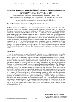
Model Descriptions The schematic diagram of the ultrafine powder centrifugal classifier used in the pr esent study is shown in Fig ure 1. C lassification wheel rotates by the driving belt, and it forms centrifugal force field in the classification chamber. The particles are subject to the centrifugal force and the fluid drag force . T he coarse particles are mainly affected by the centrifugal force, and move to the boundary. T he fine particles are mainly affected by the fluid drag force, and flow out from fine powder outlet. Coarse powder outlet is usually closed. In order to let the coarse particle flow out, need to open coarse powder outlet for a period of time wh ile classifier working. The flow media is composed by water and particles while ultrafine powder centrifugal classifier working. I t belongs to the category of liquid -solid two -phase flow, which regards the fluid as continuous medium and the particles as pseudo -fluid. B ased on the Eulerian -Eulerian liquid -solid two -phase flow model, governing equations include mass conservation equation (continuity equation) and momentum conservation equation (N -S equation) while heat exchange a nd mass exchange ignored between phase to phase [6]. The mass conservation equation of fluid phase is written as follows: ()0ufffj txj (1) The momentum conservation equation of fluid phase is written as follows: ()[()] ()uuu uupffiffjfi fifjsfuu efisii txxxxx jijji rs (2) The mass conservation equation of solid phase is written as follows: ()()ussjssstxxx jjsj (3) The mo mentum conservation equation of solid phase is written as follows: () ()[()]()[( )]uuuuu ssjsi sjssi sissss uuufsisisisjssi txxxx xxx jjjirs jsji (4) In these equations, the subscript f represents fluid phase and the subscript s represents solid phase; t represents time; is the density; u is the veloc ity; p is the pressure; e is the equivalent viscous coefficient; rs is the relaxation time of particle movement; s is the turbulent Schmidt number; vs is the turbulent diffusivity coefficient. The classification chamber is mainly constituted of classifi cation wheel, shaft and cylinder. The geometric model of classification wheel is shown in F igure 2. Pressure -Velocity Coupling was provided by the SIMPLE R method. Eulerian multiphase flow model, RNG k – Feed inletFine powder outlet Mechanical sealMotorDriving beltShaftCoarse powder outletCooling water inletCooling water outletClassification wheelOuter wall of cylinderinner wall of cylinderCylinder coverBearing pedestal Fig. 1. Schematic diagram of the ultrafine powder centrifugal classifier
PAGE – 3 ============
and multiple reference frame (MRF) m ethod were used. In order to calculate precisely, the non-equilibrium wall function was used for near -wall treatments while the second -order upwind scheme was used for discretization. Heat/mass transfer of particles was ignored when performing calculation [7] [8]. The primary phase was defined as water and the secondary phase was defined as particle (SiO 2). T he powder ™s density is 2200kg/m 3. T he inlet velocity of two -phase flow was set as 2m/s. The outlet was defined as a pressure outlet with 101,325Pa. The volume fraction of particles was set as 0.2. The rotary speed of the classification wheel was set as 1000rpm, 2000rpm and 3000rpm respectively. Simulation Results and Discussion To study the velocity distribution of axial dire ction, radial direction and tangential direction, a line named L from ( -90, 0, 0) to (90, 0, 0) was established. The positive direction of Y axis was set as the positive direction of the axial velocity. The direction from classification wheel to the wall o f cylinder was set as the positive direction of the radial velocity. The direction of classification wheel rotating was set as the positive direction of the tangential velocity. Whereas negative direction. Fig ure 3 shows the axial velocity distribution of line L. It reveals that: for different blade angles, there are no significant differences of the axial velocity distribution. The axial velocity profiles generally like wavy profiles. The maximum value appears near the center hole of the shaft. There is no large fluctuation in the classification area. Therefore, there is no obvious axial eddy -current, which is conductive to forming stable classification flow field. Figure 4 shows the radial velocity distribution of line L. There are no significant differenc es between =0°, =15° and =30° . However, the radial velocity profile of =45° varies a lot compared the above. When =45° , the values of radial velocity are positive on the left side of X=0, which is not conductive to the fine powder™s outflow. Figure 5 shows the t angential velocity distribution of line L. The particles were subject to the centrifugal force and the fluid drag force while the classifier working. Because the tangential velocity has a great influence on the values of the centrifugal force, it is very n ecessary to analyze the tangential velocity distribution in order to improve the classification efficiency. As shown in figure 8, for different blade angles, the maximum value appears at the tip of the blades. When =45° , the tangential velocity near the tip of the blades changes rapidly. It would cause the centrifugal force changing rapidly, which would affect the stability of the classification flow field. On the basis of the above discussion, when =15~30° , compared with =0°, =45° , the classification performance is the best . O n the one hand, velocity contours distribute relatively densely, which is conductive to particles dispersing and would prevent particles conglomerating; on the other hand, there are not great gradients of velocity at the tip of the blades, which is conductive to form a stable classification flow field. a) =0° b) =15 ° c) =30 ° d) =45 ° Fig. 2 The geometric model of classification wheel
PAGE – 4 ============
Investigate of Cut Size Cut size d50 is usually defined as the diameter of a spheric al particle for which the inertial centrifugal force offsets the fluid drag force, keeping the same opportunity to enter the coarse powder outlet and the fine powder outlet [9] . According to data, a number of methods have been developed to calculate the cut size in theory [ 10] [11 ]. H owever, all of these methods cannot predict the cut size precisely. In this paper, a new strategy was introduced to determine the cut size using FLUENT discrete phase model (DPM) coupled with experiments. B y using FLUENT DPM me thod, the particle trajectory and velocity could be calculated by analyze the force situation of each particle after calculating the continuous flow field. The cut size was simulated by injecting different size particles and tracking their movement [12]. T he density of the material is maintained constant at 2200kg/m 3. Since the volume fraction of the particle was set as 0.1, there is no need for momentum coupling between the solid phase and water phase. Fig ure 6 shows the particle trajectories of different diameter s while the rotary speed of the classification wheel N=1000rpm. Different colors of the particle trajectories rep resent the residence time. When the particle diameter D=0.5 , the fluid drag force is greater than the inertial centrifugal force, the particle move s inside and eventually flows out from the fine powder outlet. When D=1 , the fluid drag force offsets the inertial centrifugal force, the particle rotates in the annular region. When D=5 , the fluid drag force is smaller than the inertial centrifugal force, the particle moves outside and eventually flows out from the coarse powder outlet. Fig ure 7 shows the particle trajectories of different rotary speeds of the cla ssification wheel while the particle diameter D=0.5 . The higher the rotary speed of the classification wheel, the greater the inertial centrifugal force. The particle moves inside while N=1000rpm, rotates in the annular region while N=2000rpm, and moves outside while N=3000rpm. Fig. 3 . Axial velocity distribution Fig. 4 . Radial veloci ty distribution Fig. 5 . Tangential velocity distribution
PAGE – 5 ============
Simulation results show that, when the rotary speed of the classification wheel is 1000rpm, the cut size is close to 1 ; when the rotary speed of the classification wheel i s 2000rpm, the cut size is close to 0.5 ; when the rotary speed of the classification wheel is 3000rpm, the cut size is smaller than 0.5 . Silicon dioxide powder was selected as experimental material, and its density is 2200kg/m 3. T he experiment was cond ucted at the rotary speed of the classification wheel of 100 0rpm, 2000rpm and 3000rpm, and the inlet velocity of 2m/s. It can be seen from table 1, the simulation results well agree with the experimental data. Conclusions In su mmary, by using the numerical simulation, the present study not only analyze d the influence of different blade angles of the classification wheel on the classification flow field, but also the relationship between the cut size and the rotary speed of the c lassification wheel. Furthermore, through the experiments, the simulation results about the cut size were verified. Several conclusions can be obtained as follows: (1) By using frame (MRF) method , the influence of different blade angle s on the classification performance was studied. W hen the blade angle is 15 -30°, the classification performance is the best and the classification efficiency is highest. (2) On the basis of the analysis of the liquid -solid two -phase flow, the trajectories of each particle were studied by using discrete phase model. Simulation results shows: when the inlet velo city of two -phase flow is 2m/s and the volume fraction of the particle is set as 0.1 , the c ut size is close to 1 Fig. 7 . Particle trajectories of different rotary speeds of the classification wheel Table 1. The c omparison of the cut sizes between simulation results and experiment results Rotary speed (N) d50 of simulation results d50 of experiment results 1000rpm 1.27 2000rpm 0.62 3000rpm <0.5 0.38 Fig. 6. Particle trajectories when the rotary speed of the classification wheel N=1000rpm
PAGE - 6 ============
when the classification the classification classification wheel speed is 3000rpm. (3) The material ex periments were done with different rotary speeds of the classification wheel, and t he simulation results well agree with the experimental results. The simulation method provides a new method to predict the cut size of an u ltrafine Powder Centrifugal Classi fier , as well as various types of classifier. References [1] K.G.H. Heiskanen. Developments in wet classifiers [J]. Int. J. Miner. Process, 1996, 44(45): 29-41. [2 ] Yanchen Du, Shulin Wang . Particle trajector ies in vortex classifier rotor [J]. Journal of C hemical Industry and Engineering, 2005, 56(5): 823-828. [3] Liping Gao, Yuan Yu, Jiaxiang Liu. Study on the cut size of a turbo air classifier [J]. Powder Technology, 2013, 237: 520-528. [4 ] S. M. Mousavian, A. F. Najafi. Influence of geometry on sep arati on efficiency in a hydrocyclone [J]. Arch Appl Mech, 2009, 79: 1033-1055. [5 ] Robert Johansson, Magnus Evertsson. CFD simulation of a centrifugal air classifier used in the aggregate industry [J]. Minerals Engineering, 2014, 63: 149-156. [6] Fan Jiang, Peng Huang. Advanced application and example analysis of fluent [M] . Beijing: Tsinghua University press, 2008. [7 ] G. R. Kasata, A. R. Khopkarb. CFD simulation of liquid -phase mixing in so lid -liquid stirred reactor [J] . Chemical Engineering Science, 2008, 63: 3877-3885. [8 ] Hongzhi Yan , Xinming Li, Bo Wu, et al. Numerical analysis of liquid -solid two -phase in horizontal biaxial stirred tank [J]. Journal of Central South University (Science and Technology), 2013, 44(2): 533-539. [9 ] Huizhong Liu , Rongtian Zhen . Hydraulic (wet) classification technology of fine particle [J]. Mining & Metallurgy, 2005, 14(3): 26-29. [10] Jiaxiang Liu, Jingbo Xia, Tingshu He, Air flow field characteristics analyzing and classification process of the turbo classifier [J]. Journal of the Chinese Ceramic Society , 2003, 31: 485-489. [11] Tao Ye, Xu. Ning, Zhichu Huang, et al. Experimental investigation on classified particles cut size of turbo air classifi er [J]. Mining & Processing Equipment, 2006, 34: 62-63. [12 ] Cong Tong , Shuangyue Li, Xiang Li. Numerical simulation on particles classification trajectory using unsteady tracking [J]. Chemical Industry and Engineering Progress, 2013, 32(9): 2061-2067.
161 KB – 6 Pages