BELT BEATER. Increases Belt Life – Application Guide. BACKGROUND. Cleaning material from cleated belts has long been a problem for the conveyor industry.
180 KB – 6 Pages
PAGE – 1 ============
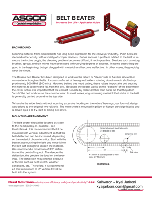
BELT BEATER Increases Belt Life – Application GuideBACKGROUND Cleaning material from cleated belts has long been a problem for the conveyor industry. Plain belts are cleaned rather easily with a variety of scraper devices. But as soon as a pro˜le is added to the belt to in -crease the incline angle, the cleaning problem becomes dif˜cult, if not impossible. Devices such as rotary brushes, sprays, and air knives have been used with varying degrees of success. In some cases they are good in the beginning, but get clogged with material and become ineffective. In other cases, they rapidly wear the cleats.The Bassco Belt Beater has been designed to work on the return or ficleanfl side of ˚exible sidewall or conventional troughed belts. It consists of a set of heavy wall rollers, rotating about a main shaft at ap -proximately 600 RPM (540 min.). Mounted behind the head pulley, these rollers impact the belt causing the material to loosen and fall from the belt. Because the beater works on the fibottomfl of the belt where the cover is thin, it is important that the contact is made by rollers (rather than bars), so that they don™t fiscrubfl the belt and cause the cover to wear. In most cases, any remaining material that sticks to the belt is generally carried around to the top side.To handle the wider belts without incurring excessive loading on the rollers™ bearings, our four-roll design was added to the original two-roll unit. The main shaft is mounted in pillow or ˚ange cartridge blocks and is driven by a 3 to 1 V-belt or timing belt drive. MOUNTING ARRANGEMENTThe belt beater should be located as close to the head pulley as possible – see Illustration A. It is recommended that it be mounted with vertical adjustment so that the belt de˚ection can be increased, depending on the material characteris-tics. Start with the beater just touching the belt and move it into the belt just enough to loosen the material. We recommend a maximum of 3/8fl de˚ec -tion at the point of impact. The deeper the de˚ection, the greater the load on the bear-ings. The de˚ection may change because of factors such as belt stretch, weather conditions, etc. Therefore, it is recommend-ed that a minimum of 2fl vertical travel be built into the system.Vertical adjustment should allow up to Dampening Idler2XflXfl Illustration A6fl
PAGE – 2 ============
Because of the wide variety of pulley sizes and frame designs, and the fact that the return side of the belt can range from 15™™ below the channel frame to 15™™ above, ASGCO has designed a fiuniversalfl mounting bracket, with 2fl of vertical adjustment, that will ˜t most installations – even those which require the beater drive shaft to project through the frame member. A layout should be made for each installation to deter -mine the proper requirements.SelectionThe ˜rst step is to decide which of the two sizes will ˜t your application. The 2-roll beater is generally used on all belt widths up through 36fl – 42™™ width. It is powered with a 2 HP (3 HP optional) motor. The 4-roll design is used for belts 42fl wide and up, and for sticky materials. It has a 5 HP drive. A 7.5 HP drive is recommended for 60flwide belts and wider, along with the use of roller bearings for the main shaft. The standard reduction is V-belt, with timing belt drive as an option. Note that the motor mount is also vertically adjustable to match the travel of the beater main shaft. The next step is to determine the dimensional relationship between the return side of the belt and the frame. Refer to the table below as a guide to the mounting arrangement that you will require. A = Distance from the top of the return side of the belt to the nearest part of the frame. Arrangement 1Belt to bottom of frameBelt to bottom of frame2-Roll A=5 1/2fl or More4-Roll A=6 3/4fl or More2-Roll A=2 1/2fl or Less 4-Roll A=3 1/4fl or Less For application between #1 and #2 aboveSelect universal mountSelect universal or foot mounted bracketsUniversal mount will work with a hole in frame for the main shaft. Contact ASGCO Arrangement 2Arrangement 32
PAGE – 3 ============
Mounting Brackets The fiuniversalfl mounting brackets (see below) are supplied broken down in fikitfl form so that they can be installed in a variety of ways to ˜t most installation requirements. The brackets have mounting slots to allow for latitude in the attachment of the bracket to the frame. Each bracket has four mounting slots. We recommend that four bolts be used to attach the beater brackets to the frame. In some layouts, an additional support plate may have to be added to the top or bottom of the frame to fasten the brackets securely. If the toes of the channel frame are pointed in, you may want to mount the brackets with the toes in to provide space to get wrenches in place on the bearing bolts. If the drive motor interferes with the carrying side of the belt, you can reposition the motor base to the second mounting location which moves it outward 2™™ (see Position 2 above). Make sure that the main drive shaft is also 2™™ longer. If the motor still interferes with the belt, rotate the brackets 180° (see Illustration C below).2 1/2fl5 5/8fl 10 5/8flBolt inAdjustment ScrewBrg PlateWith FlangeCartridge Bearing13 1/2flPOS #2Drive Shield92 POS #1Drive Shield1115UP POS 2 1/2fl2 1/2flAs Req™d3
PAGE – 4 ============
4When using the inverted installation, be sure to install the adjusting screw above the ˚ange bearing. For special conditions, contact ASGCO for other available bracket designs. If neither of the above arrangements will work, or if your frame is enclosed, ASGCO offers a foot mounted bracket design that requires a base to be added to the conveyor structure. See illustration D. Check your shaft length to be sure it is long enough.Illustration CIllustration D
PAGE – 5 ============
ARoll Face Belt Width +2flBelt Width +2flBeaters Only (Less Drive And Pillow Blocks) If you wish to supply your own drive and mounting brackets, select the proper size for your application. Determine the overall shaft length to ˜t your drive design. Dampening Roll Assemblies At 600 RPM, belt beaters will impact the belt 1200 times a minute. This will cause the belt to vibrate in a sine wave fashion that will often be carried into the frame. In order to reduce or eliminate these vibra -tions, ASGCO has designed an assembly that consists of two pair of zero degree stub idlers and a ˚at roll that fisandwichfl the belt. The assembly is designed to accommodate various belt thicknesses. Like the regular stub idlers, each is manufactured to ˜t the belt recess and drop/rise dimension, and requires only four bolts to attach it to the frame. It should be mounted as close to the beater as possible. For situations where the shaft projects through the frame, oversized idler rolls are often required to reach the belt. A layout will indicate the proper diameter. 2-Roll 4-Roll BCDEOAL Beater Assy. C/L Brg. Mnting. HolesStandard Shaft Length Beater HeightShaft DiameterApprox. Wt. Belt Width +9flBelt Width +9flBelt Width +22flBelt Width +22fl9.125fl 11fl1 15/16fl Turned to 1 7/16fl2 7/16fl Turned to 1 15/16fl375 + 23lbs per inch of belt width400 + 28lbs per inch of belt widthBelt Width +6 3/8flBelt Width +7 3/8fl5
180 KB – 6 Pages