by P Frank · 2011 · Cited by 5 — check valve to a pressure release mineral oil bubbler (beyond 3; see pg. inert gas for a Schlenk line is either an external gas cylinder.
8 pages
135 KB – 8 Pages
PAGE – 1 ============
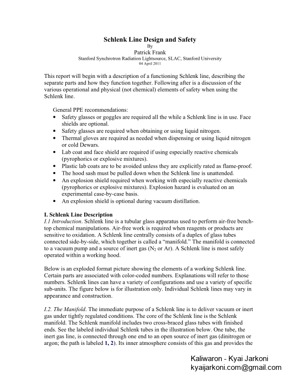
1Schlenk Line Design and Safety By Patrick Frank Stanford Synchrotron Radiation Lightsource, SLAC, Stanford University 04 April 2011 This report will begin with a description of a functioning Schlenk line, describing the separate parts and how they function together. Following after is a discussion of the various operational and physical (not chemi cal) elements of safety when using the Schlenk line. General PPE recommendations: • Safety glasses or goggles are required all the while a Schlenk line is in use. Face shields are optional. • Safety glasses are required when obtaining or using liquid nitrogen. • Thermal gloves are required as needed wh en dispensing or using liquid nitrogen or cold Dewars. • Lab coat and face shield are required if using especially reactive chemicals (pyrophorics or explosive mixtures). • Plastic lab coats are to be avoided unless they are explicitly rated as flame-proof. • The hood sash must be pulled down when the Schlenk line is unattended. • An explosion shield required when working with especially reactive chemicals (pyrophorics or explosive mixtures). Explosion hazard is evaluated on an experimental case-by-case basis. • An explosion shield is optional during vacuum distillation. I. Schlenk Line Description I.1 Introduction. Schlenk line is a tubular glass appa ratus used to perform air-free bench- top chemical manipulations. Air-free work is required when reagents or products are sensitive to oxidation. A Schlenk line centrally consists of a duplex of glass tubes connected side-by-side, which together is called a fimanifold. fl The manifold is connected to a vacuum pump and a source of inert gas (N 2 or Ar). A Schlenk line is most safely operated within a working hood. Below is an exploded format picture showing the elements of a working Schlenk line. Certain parts are associated with color-coded numbers. Explanations will refer to those numbers. Schlenk lines can have a variety of configurations and use a variety of specific sub-units. The figure below is for illustration only. Individual Schlenk lines may vary in appearance and construction. I.2. The Manifold. The immediate purpose of a Schlenk line is to deliver vacuum or inert gas under tightly regulated conditions. The core of the Schlenk line is the Schlenk manifold. The Schlenk manifold includes two cross-braced glass tubes with finished ends. See the labeled individual Schlenk tubes in the illustration below. One tube, the inert gas line, is connected through one end to an open source of inert gas (dinitrogen or argon; the path is labeled 1, 2). Its inner atmosphere consists of this gas and provides the
PAGE – 2 ============
2dynamic gas supply to the Schlenk user. The exce ss gas delivered to this side exits past a check valve to a pressure release mineral o il bubbler (beyond 3; see pg. 4). An optional ballast bulb at the back end (11) increases the volume of this line. The mineral oil bubbler (see pg. 4) also acts as a barrier between the inert internal atmosphere of the line, and the external oxidizing atmosphere. The other Schlenk tube, the vacuum side, is connected to an operating vacuum pump through the forward end (at 4) and supplies dynamic vacuum to the Schlenk user. The Schlenk vacuum side is evacuated th rough a liquid nitrogen-cooled trap (5, 7), which in turn connects to the vacuum pump (beyond 6). The cold trap condenses evacuated organic vapors as ices, preventing their entr y into the pump or into the lab atmosphere. The tube-end connections at 2, 4, 8, and 11 are sealed using compressible o-rings situated between the glass connectors. The two halves of the glass connection are fixed together using spring-loaded U-clamps, illustrated below. 5
PAGE – 3 ============
3The vacuum line and the inert gas line each have a spaced set of high-vacuum two-way valves (vacuum and gas). These reduce dow n to a common exit, which is typically finished with a connection port for rubber tubing (8, 9). This system is illustrated as the four valves projecting downwards from the Schlenk manifold in the illustration above. One or the other valve delivers vacuum or inert gas, as desired, to its common exit (8). Finally, the gas or vacuum is delivered from the outlet of the two-way valve through a vacuum tubing line ( 9) to the user. That is, depending on the orientation of the two-way valve, either vacuum or inert gas (or neith er) is made available at the end of tube 9. The picture below shows an operational Schlenk line with all the parts assembled. Operational Schlenk Line The depending black vacuum hoses deliver vacuum or inert gas. The pump on the far right delivers vacuum to the Schlenk manifold through the vacuum trap and its blue- jacketed Dewar. Not eviden t are a pressure-release bubbler or a ballast bulb. Application of vacuum or in ert gas to a chemical transf ormation is made by connecting tube 9 to the side-arm of the Schlenk flask ( 10). The side arm of this flask is equipped with its own high-vacuum valve, which provides or blockades external access when the mouth of the Schlenk flask is stoppered. The mouth of the Schlenk flask can be closed with either a precision glass stopper or with a rubber serum stopper (shown), depending on need. Note the adjoining cork ring (12) built to accept the bottom of the Schlenk flask. Use of a cork ring to support glass Schlenk flasks prevents an y weight-bearing by the bottom-most surface of the flask. This in turn prevents chance star cracking of the flask. On a flat surface, round bottom flasks rest wi th all their weight on a small surface area. Star-cracks are induced by a particle of grit or sand under the small contact surface. This completes the basic descrip tion of a generic Schlenk line. II. Schlenk Line Physical Safety Physical safety will be the primary concern of this analysis. Chemical safety will be touched upon only in general terms and as rele vant to physical safety. Schlenk lines are constructed of Pyrex-quality tubular glass. With this combination, Schlenk lines are highly resistant to trans-wall pressure diffe rentials; especially to external positive (compressional) pressure.
PAGE – 4 ============
4II.1. Pressure. The source of inert gas for a Schlenk line is either an external gas cylinder or a house supply. In either case, the gas should be delivered to the Schlenk line through a two-stage regulator. Each stage of the regulator registers a positive pressure that is above the pressure of the ambient external at mosphere. That is, atmo spheric pressure is the fizero pressurefl of the regul ator scale and all pressures ar e measured relative to this zero. The setting of the source gas regulator establishes the positive pressure of the Schlenk inlet gas. The precision of a second stage regulator should allow a pressure setting to within about ±2 psi. About 10 ps i of positive pressure is an adequate second stage regulator setting, with needle valve delivery. Fine control of the final inflow rate of the inert gas is achieved using a needle valve. Operating a Schlenk line often requires turning gas flow up or down, depending on immediate need. This level of control is not possible without a needle valve between the regulator and the Schlenk line. Caution 1: A needle valve determines the rate at which the internal pressure of a closed-system Schlenk line rises to the pressure setting of the regulator second stage. Absent a needle valve, a closed-system Schlenk line will pressurize up immediately when the inert gas suppl y is opened. Shock-pressurization may be hazardous if the Schlenk line has de veloped a glass defect, or if the regulator second stage had been changed to a high pressure setting between Schlenk line uses. II.1.2. Pressure Release and Check Valve Schlenk lines are safer when the internal posi tive pressure within the inert gas side is ideally set by the height of the liquid column within a pressure release bubbler. See the illustration below. Absent a pressure release bubbler, the internal pressure is finally established by the setting on the second regulator stage. In the past, about 80 cc of liquid mercury (Hg) in a ~10 cm column was the bubbler liquid of choice for Schlenk pressure release. The configuration was different than shown in the picture below, however, the effect was the same. Pressure Release Bubbler A 10 cm pressure by-pass column of mercur y (density 13.5 gm/cc) maintains a Schlenk line internal pressure of a bout 2 psi of positive pressure. At the same time, positive pressures in excess of 2 psi cause inert gas to flow past the liquid mercury. This obviates internal pressure build-up, while disallowing back-flow of air into the Schlenk system.
PAGE – 5 ============
5 If any inadvertent vacuum fault is committed against the inert gas side of the Schlenk line, the density of mercury allows only a sl ow pull-back of liquid from the bubbler. This slow response allows an operator time to rec over from a vacuum fault before air is pulled back into the Schlenk line inert atmosphere. To explain a vacuum fault: looking at the bubbl er in the Figure above, the fiGas infl port receives a flow of gas from the inert atmosphere line of the Schlenk manifold. In a vacuum fault, the inert atmosphere line is inadvertently evacuated. The fiGas infl side of the bubbler is then likewise evacuated, and gas flow is reversed through the bubbler. Air enters the fiGas outfl port, and the differential pressure pushes the mineral oil up the small inner bubbler tube, and into the fiGas infl arm. Continued ev acuation will pull the mineral oil fully up the bubbler tube, where it passes out the fiGas infl port and enters the inert atmosphere line of the Schlenk manifold. The mineral oil will be followed by air. Entry of air into the Schlenk manifold will destr oy the inert atmosphere, and almost certainly ruin any attached experiment. Any pyrophoric or flammable materials may be thereby exposed to air. The slow response of high density mercury bubblers to back-flow reduces the number of severe-consequence vacuum faults. In this sense, a mercury bubbler pressure release provides more safety than an oil bubbl er. However, mercury bubblers are no longer permitted. The mineral oil in a replacement bubbler has a density of about 0.8 gm/cc and vacuum pump oil has a density of about 0.87 gm/cc. A 10 cm bubbler column of mineral oil or vacuum pump oil maintains about 0.13 ps i of internal pressure within the inert atmosphere line of a Schlenk manifold. In contrast to the case with liquid mercury, a vacuum fault will rapidly pull low-density oil back into a Schlenk manifold. Therefore, a check valve between the bubbler and the Schlenk inert atmosphere line is a necessary addition to oil based pressure-release systems. The check valve closes against any inadvertent vacuum in the inert atmosphe re Schlenk line, blockading oil back-flow. Any check-valve so used must necessarily not compromise the inert atmosphere. The check valve must therefore be itself sealed against air. Caution 2. Check-valve use is a safety issue because, as noted above, unrestricted back-flow will quickly bring air into a Schlenk line, where it will contact the chemicals in use. If a pyrophoric chemi cal is in use, ignition may occur on exposure to oxygen. Caution 3. Continued backflow of air through the Schlenk line will introduce air into the liquid nitrogen traps where it may conde nse into liquid air. Liquid air in the trap and in contact with organic ices or residues is an imminent explosion hazard. II.2 Vacuum. The vacuum source for a Schlenk manifo ld is typically a vacuum pump. To a large degree, the differential pressure across the walls of the Schlenk line is invariant, no matter what sort of pump is used. For ex ample, a water pump that achieves a rough
PAGE – 6 ============
6vacuum of 17.5 torr* of residual internal pressu re (i.e., the vapor pressure of water at 20 C), produces a pressure differential across the walls of the Schlenk vacuum line of 0.98 atm = 14.4 lb/in 2 (1.02 kg/cm2). In comparison, an efficien t oil pump that achieves 100 millitorr of residual internal pressure, produ ces a pressure differential of 0.9999 atm = 14.7 lb/in2 (1.04 kg/cm2). The achieved difference on the Schlenk line of 0.3 lb/in2 pressure gradient (2%) is relatively trivial. *1 torr = 1/760 of atmospheric pressure. Unde r standard conditions, a 760 mm column of mercury exerts 1 atmosphere of pressure. II.2.1. The vacuum line. The tubular structure of the Schlenk line is resistant to circularly uniform external pressure gradients across th e walls. The vacuum hazard associated with Schlenk lines is therefore implosion due to glass failure. Implosions can be violent and can produce high velocity glass shrapnel. Caution 4. A glass flaw on the vacuum side constitutes an implosion hazard. Therefore, Schlenk lines must be visually inspec ted, especially during and immediately after installation. Cracks of any sort should be repaired by a competent glass blower. All repairs should be annealed. Caution 5. Cracks can arise in the glass seat of Teflon (ptfe) high-vacuum valves when they are over-tightened. Failure of a valve seat during evacuated operation may cause an implosion. The typical symptom of a cracked valve seat is that the Schlenk line cannot achieve vacuum. Teflon high vacuum valves seal efficiently when only finger tight. II.2.2. Glassware. Schlenk round bottoms (item 10 in the first illustration) can develop star cracks if directly seated on the floor of the hood during use, or if directly seated on a heating or stirring plate. Caution 6. Star cracks in Schlenk flasks or in other evacuable glassware can produce an implosion on evacuation. In use, a Schlenk flask should rest on a cork ring (item 12, illustration 1), or be supported using a clamp attached to a trellis rack or a ring-stand. The caution regarding star cracks is pertinent to all evacuable glass Schlenk apparatus, including fritted Schlenk filters and vacuum stills. They should all be visually inspected before use. All subsidiary and evacuable Schlenk glassware, such as flasks and funnels, should be visually examined for cracks, star cracks, a nd glass defects prior to every use. Schlenk lines themselves are suspended and are typica lly not subject to the impacts associated with washing and drawer storage. Well-constructed and tempered Schlenk lines are generally robust against cracks, except around over-tightened ptfe vacuum valve seats, as noted above.
PAGE – 8 ============
8 Glass Dewars should have a plastic safety jacket, or be wrapped in a plastic tape such as electrical tape. The implosion hazard of glass Dewars can be obviated by exclusive use of stainless steel Dewars. Dewar flasks, whether glass or stainless steel, are typically filled with liquid nitrogen. When filling Schlenk trap Dewars in place around a warm vacuum trap, liquid nitrogen will sputter out more than when filling an empty free-standing Dewar. The reason is that the liquid nitrogen is in contact with both the warm Dewar wall, and the warm glass of the vacuum trap. Liquid nitrogen will vigor ously boil off in the small space between the inner wall of the Dewar and the outer wall of the glass trap. Vigorous surface ebullition can strongly vault sprays of liquid nitrogen. Filling the trap Dewar too quickly can result in a boil-up of liquid nitrogen spraying out over the side of the Dewar. Caution 11. Liquid nitrogen vaulting from a trap -Dewar combination is a freeze hazard, especially to the eyes. After use with liquid nitrogen, Schlenk trap Dewars are typically very cold around the upper rim. Caution 12. An incautious grip while lowering a cold vacuum trap Dewar, e.g., without thermal gloves, can produce a frostbitten thumb or finger. Cold vacuum trap Dewars should always be supported from the bottom, and gripped at the side.
135 KB – 8 Pages