Obey the manual for the air compressor used to power this tool. 6. Install an in-line shutoff valve to allow immediate control over the air supply in an.
293 KB – 20 Pages
PAGE – 1 ============
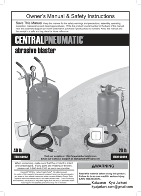
Read this material before using this product. Failure to do so can result in serious injury. SAVE THI S MANUAL.Copyright© 2012 by Harbor Freight Tools ®. All rights reserved. No portion of this manual or any artwork contained herein may be reproduced in any shape or form without the express written consent of Harbor Freight Tools. Diagrams within this manual may not be drawn proportionally. Due to continuing improvements, actual product may differ slightly from the product described herein. Tools required for assembly and service may not be included. When unpacking, make sure that the product is intact and undamaged. If any parts are missing or broken, please call 1-800-444-3353 as soon as possible.Save This Manual Keep this manual for the safety warnings and precautions, assembly, operating, inspection, maintenance and cleaning procedures. Write the product™s serial number in the back of the manual near the assembly diagram (or month and year of purchase if product has no number). Keep this manual and the receipt in a safe and dry place for future reference.Owner™s Manual & Safety Instructions Visit our website at: http://www.harborfreight.com Email our technical support at: tech@harborfreight.comITEM 68994abrasive blasterITEM 6899240 lb.20 lb.
PAGE – 2 ============
Page 2For technical questions, please call 1-800-444-3353.Item 68992 68994Table of ContentsSafety 2Specifications 6Setup .7Operation 14Maintenance .16Parts Lists and Diagrams ..18Warranty .20WARNING SYMBOLS AND DEFINITIONSThis is the safety alert symbol. It is used to alert you to potential personal injury hazards. Obey all safety messages that follow this symbol to avoid possible injury or death.Indicates a hazardous situation which, if not avoided, will result in death or serious injury. Indicates a hazardous situation which, if not avoided, could result in death or serious injury. Indicates a hazardous situation which, if not avoided, could result in minor or moderate injury. Addresses practices not related to personal injury. IMPORTANT SAFETY INSTRUCTIONSINSTRUCTIONS PERTAININ G TO A RI SK OF FIRE, ELECTRIC SHOCK, OR INJURY TO PERSONSWARNING ΠWhen using tools, basic precautions should always be followed, including the following:GeneralTo reduce the risks of electric shock, fire, and injury to persons, read all the instructions before using the tool. Work Area1. Keep the work area clean and well lighted. Cluttered benches and dark areas increase the risks of electric shock, fire, and injury to persons.2. Do not operate the tool in explosive atmospheres, such as in the presence of flammable liquids, gases, or dust. The tool is able to create sparks resulting in the ignition of the dust or fumes.3. Keep bystanders, children, and visitors away while operating the tool. Distractions are able to result in the loss of control of the tool.SAFETYOPERATI ONMAINTENANCESETUP
PAGE – 3 ============
Page 3For technical questions, please call 1-800-444-3353.Item 68992 68994Personal Safety1. Stay alert. Watch what you are doing and use common sense when operating the tool. Do not use the tool while tired or under the influence of drugs, alcohol, or medication. A moment of inattention while operating the tool increases the risk of injury to persons.2. Dress properly. Do not wear loose clothing or jewelry. Contain long hair. Keep hair, clothing, and gloves away from moving parts. Loose clothes, jewelry, or long hair increases the risk of injury to persons as a result of being caught in moving parts.3. Avoid unintentional starting. Be sure the switch is off before connecting to the air supply. Do not carry the tool with your finger on the switch or connect the tool to the air supply with the switch on.4. Do not overreach. Keep proper footing and balance at all times. Proper footing and balance enables better control of the tool in unexpected situations.5. Use safety equipment. A dust mask, non-skid safety shoes and a hard hat must be used for the applicable conditions.6. Always wear eye protection. Wear ANSI-approved safety goggles.7. Always wear hearing protection when using the tool. Prolonged exposure to high intensity noise is able to cause hearing loss.8. Wear heavy-duty work gloves during use. Tool Use and Care1. Use clamps or another practical way to secure and support the workpiece to a stable platform. Holding the work by hand or against the body is unstable and is able to lead to loss of control.2. Do not force the tool. Use the correct tool for the application. The correct tool will do the job better and safer at the rate for which the tool is designed.3. Do not use the tool if the switch does not turn the tool on or off. Any tool that cannot be controlled with the switch is dangerous and must be repaired.4. Disconnect the tool from the air source before making any adjustments, changing accessories, or storing the tool. Such preventive safety measures reduce the risk of starting the tool unintentionally. Turn off and detach the air supply, safely discharge any residual air pressure, and release the throttle and/or turn the switch to its off position before leaving the work area.5. Store the tool when it is idle out of reach of children and other untrained persons. A tool is dangerous in the hands of untrained users.6. Maintain the tool with care. Keep a cutting tool sharp and clean. A properly maintained tool, with sharp cutting edges reduces the risk of binding and is easier to control.7. Check for misalignment or binding of moving parts, breakage of parts, and any other condition that affects the tool’s operation. If damaged, have the tool serviced before using. Many accidents are caused by poorly maintained tools. There is a risk of bursting if the tool is damaged.8. Use only accessories that are identified by the manufacturer for the specific tool model. Use of an accessory not intended for use with the specific tool model, increases the risk of injury to persons.Service1. Tool service must be performed only by qualified repair personnel.2. When servicing a tool, use only identical replacement parts. Use only authorized parts.3. Use only the lubricants supplied with the tool or specified by the manufacturer. Do not use any lubricants with this tool.SAFETYOPERATI ONMAINTENANCESETUP
PAGE – 4 ============
Page 4For technical questions, please call 1-800-444-3353.Item 68992 68994Air Source1. Never connect to an air source that is capable of exceeding 200 psi. Over pressurizing the tool may cause bursting, abnormal operation, breakage of the tool or serious injury to persons. Use only clean, dry, regulated compressed air at the rated pressure or within the rated pressure range as marked on the tool. Always verify prior to using the tool that the air source has been adjusted to the rated air pressure or within the rated air-pressure range.2. Never use oxygen, carbon dioxide, combustible gases or any bottled gas as an air source for the tool. Such gases are capable of explosion and serious injury to persons. SAVE THE SE INSTRUCTIONS.Symbols and Specific Safety InstructionsSymbol DefinitionsSymbolProperty or statementnoNo-load speed/minRevolutions or reciprocation per minutePSIPounds per square inch of pressureft-lbFoot-pounds of torqueBPMBlows per minuteCFMCubic Feet per Minute flowSCFMCubic Feet per Minute flow at standard conditionsSymbolProperty or statementNPTNational pipe thread, taperedNPSNational pipe thread, straightWARNING marking concerning Risk of Eye Injury. Wear ANSI-approved eye protection.WARNING marking concerning Risk of Hearing Loss. Wear hearing protection. WARNING marking concerning Risk of Respiratory Injury. Wear NIOSH-approved dust mask/respirator. WARNING marking concerning Risk of Explosion.Specific Safety Instructions1. The warnings and precautions discussed in this manual cannot cover all possible conditions and situations that may occur. It must be understood by the operator that common sense and caution are factors which cannot be built into this product, but must be supplied by the operator. 2. WARNING: This product, when used for abrasive blasting and similar applications, produces chemicals known to the State of California to cause cancer and birth defects (or other reproductive harm). (California Health & Safety Code § 25249.5, et seq.) WARNING: The brass components of this product contain lead, a chemical known to the State of California to cause birth defects (or other reproductive harm). (California Health & Safety code § 25249.5, et seq.)3. Only use with accessories rated to handle the forces exerted by this tool during operation. Other accessories not designed for the forces generated may break and forcefully launch pieces.4. Attach all accessories properly to the tool before connecting the air supply. A loose accessory may detach or break during operation.SAFETYOPERATI ONMAINTENANCESETUP
PAGE – 5 ============
Page 5For technical questions, please call 1-800-444-3353.Item 68992 689945. Obey the manual for the air compressor used to power this tool.6. Install an in-line shutoff valve to allow immediate control over the air supply in an emergency, even if a hose is ruptured.7. Use this tool with both hands only. Using tools with only one hand can result in loss of control.8. Do not lay the tool down until it has come to a complete stop. Moving parts can grab the surface and pull the tool out of your control.Silicosis and Aluminum Oxide Warnings WARNING! Abrasive blasting with sand containing crystalline silica can cause serious or fatal respiratory disease. Exposure to crystalline silica may cause silicosis (a serious lung disease), cancer and death. Exposure to aluminum oxide (a dust generated from material removing processes) can result in eye, skin and breathing irritation. Always use a NIOSH (National Institute for Occupational Safety and Health) approved respirator and safety goggles. Avoid skin exposure. Proper ventilation in the work area is required. Read and understand the 10 recommended measures below to reduce crystalline silica exposures in the workplace and prevent silicosis and silicosis related deaths.NIOSH recommends the following measures to reduce crystalline silica exposures in the workplace and prevent silicosis and silicosis-related deaths:1. Prohibit silica sand (or other substances containing more than 1% crystalline silica) as an abrasive blasting material and substitute less hazardous materials.2. Conduct air monitoring to measure worker exposures. 3. Use containment methods such as blast-cleaning machines and cabinets to control the hazard and protect adjacent workers from exposure.4. Practice good personal hygiene to avoid unnecessary exposure to silica dust.5. Wear washable or disposable protective clothes at the work site. Shower and change into clean clothes before leaving the work site to prevent contamination of cars, homes and other work areas.6. Use respiratory protection when source controls cannot keep silica exposures below the NIOSH REL.7. Provide periodic medical examinations for all workers who may be exposed to crystalline silica.8. Post signs to warn workers about the hazard and to inform them about required protective equipment.9. Provide workers with training that includes information about health effects, work practices and protective equipment for crystalline silica.10. Report all cases of silicosis to State health departments and to OSHA or the Mine Safety and Health Administration (MSHA). Vibration PrecautionsThis tool vibrates during use. Repeated or long-term exposure to vibration may cause temporary or permanent physical injury, particularly to the hands, arms and shoulders. To reduce the risk of vibration-related injury: 1. Anyone using vibrating tools regularly or for an extended period should first be examined by a doctor and then have regular medical check-ups to ensure medical problems are not being caused or worsened from use. Pregnant women or people who have impaired blood circulation to the hand, past hand injuries, nervous system disorders, diabetes, or Raynaud’s Disease should not use this tool. If you feel any symptoms related to vibration (such as tingling, numbness, and white or blue fingers), seek medical advice as soon as possible.2. Do not smoke during use. Nicotine reduces the blood supply to the hands and fingers, increasing the risk of vibration-related injury. 3. Wear suitable gloves to reduce the vibration effects on the user. 4. Use tools with the lowest vibration when there is a choice.5. Include vibration-free periods each day of work.6. Grip tool as lightly as possible (while still keeping safe control of it). Let the tool do the work.7. To reduce vibration, maintain tool as explained in this manual. If abnormal vibration occurs, stop immediately. SAVE THE SE INSTRUCTIONS.SAFETYOPERATI ONMAINTENANCESETUP
PAGE – 6 ============
Page 6For technical questions, please call 1-800-444-3353.Item 68992 68994Functional DescriptionSpecificationsItem6899268994Air Pressure60~125 PSIMaximum Air Pressure 125 PSIAir InletAverage Air Consumption 6~25 CFMRequired Air Hose Abrasive Capacity40 lb.20 lb.NozzleTrigger Valve Abrasive Valve Throttle Valve Air Valve Filler CapSafety Valve Figure A : 68992 Components and ControlsNozzleTrigger Valve Abrasive Valve Throttle Valve Air Valve Filler CapSafety Valve Figure B: 68994 Components and ControlsSAFETYOPERATI ONMAINTENANCESETUP
PAGE – 8 ============
Page 8For technical questions, please call 1-800-444-3353.Item 68992 68994Figure E Handlebars (6)Nut (9)Handle Grips (7)Bolts (8)Abrasive Hose (24)7. Slide Handle Grips (7) onto the Handlebars (6). See Figure E.8. Attach Handle Bars to Tank using Bolts (8) and Nuts (9). The Handle Bars must curve back and the holes at the bottom must be parallel to each other. See Figure E.9. Slide open end of Abrasive Hose (24) onto Abrasive Outlet Pipe (22). Secure in place using Clamp (23).Figure F Wheel (2)Cotter Pin (3)Foot (4)Cotter Pin (3)Axle (5)10. Attach the Foot (4) to the Tank using a Cotter Pin (3). See Figure F.11. Attach one Wheel (2) to the Axle (5) using a second Cotter Pin.12. Slide the Axle through the holes in the bottom of the Handlebars.13. Attach the other Wheel to the Axle using the remaining Cotter Pin.Safety Valve (10) Tank (1) Figure G 14. Thread the Safety Valve (10) into the hole at the top of the Tank. WARNING! TO PREVENT SERIOUS INJURY AN D DEATH FROM EXPLOSION: Do not thread anything other than the Safety Valve (10) into the hole provided at the top of the Tank (1).15. After assembly, use a wrench to make sure all threaded connections are tight.Item 68992SAFETYOPERATI ONMAINTENANCESETUP
PAGE – 9 ============
Page 9For technical questions, please call 1-800-444-3353.Item 68992 6899468994 Assembly InstructionsNote: Wrap 3 to 4 turns of thread seal tape on all airline connections. Make sure all joints are securely tightened. Note: For additional information regarding the parts listed in this section, refer to the 68994 Parts List and Diagram on page 19.1. Place the Tank (1) on a table. Figure H Table 21342. Slide each Leg (4) onto a post as shown in Figure H, and secure with a Cotter Pin (3).3. Thread the Safety Valve (2) into the hole at the top of the Tank (1). WARNING! TO PREVENT SERIOUS INJURY AN D DEATH FROM EXPLOSION: Do not thread anything other than the Safety Valve (2) into the hole provided at the top of the Tank (1).Figure I 4. Assemble the Air Inlet assembly (see Figure I):a. Thread the Pipe (7) into the Air Valve (11). b. Thread the Nipple Connector (9) into the other side of the Air Valve (11). c. Thread the other end of the Nipple Connector (9) into the T-Connector (8). d. Thread the Air Inlet (10) into the other side of the T-Connector (8). e. Thread another Nipple Connector (9) into the bottom of the T-Connector (8). f. Thread a Throttle Valve (11A) onto that Nipple Connector (9).g. Thread the Hose Connector (12) into the Throttle Valve (11A). Figure J 5. Thread the Air Inlet assembly into the top of the Tank as shown in Figure J.6. Attach the Air Hose (13) to the Hose Connector (12). Figure K 7. Assemble one end of a Nipple Connector (9) into the Abrasive Outlet Pipe (22), and the other end into the Abrasive Valve (11B). See Figure K.8. Thread another Nipple Connector (9) into the other end of the Abrasive Valve (11B), and then thread it into the Tank (1). Item 68994SAFETYOPERATI ONMAINTENANCESETUP
PAGE – 10 ============
Page 10For technical questions, please call 1-800-444-3353.Item 68992 68994Figure L 9. Assemble the Nozzle Assembly (see Figure L):a. Thread the Nozzle Valve (11C) onto the Adapter (16).b. Thread a Nipple Connector (9) into the other side of the Nozzle Valve (11C). c. Onto the other end of the Nipple Connector (9), add Nozzle Gasket (19) and a Nozzle (18A Π18D).d. Thread the Nozzle Capnut (17) on over the Nozzle.Figure M 141615142210. Attach the nozzle assembly to the Abrasive Hose (15), using the Clamp (14) to secure them together. 11. Use another Clamp (14) to attach the other end of the Abrasive Hose (15) to the Abrasive Outlet Pipe (22). See Figure M.12. Connect the Air Hose (13) to the Abrasive Outlet Pipe (22).13. After assembly, use a wrench to make sure all threaded connections are tight.Item 68994SAFETYOPERATI ONMAINTENANCESETUP
PAGE – 11 ============
Page 11 For technical questions, please call 1-800-444-3353.Item 68992 68994Air SupplyTO PREVENT SERIOUS INJURY FROM EXPLOSION: Use only clean, dry, regulated, compressed air to power this tool. Do not use oxygen, carbon dioxide, combustible gases, or any other bottled gas as a power source for this tool.1. Incorporate a filter, regulator with pressure gauge, dryer, in-line shutoff valve, and quick coupler for best service, as shown on Figure N on page 12 and Figure O on page 13. An in-line shutoff ball valve is an important safety device because it controls the air supply even if the air hose is ruptured. The shutoff valve should be a ball valve because it can be closed quickly. Note: An oiler system should not be used with this tool. The oil will mix with the material being propelled, causing poor results.2. Attach an air hose to the compressor’s air outlet. Connect the air hose to the air inlet of the tool. Other components, such as a coupler plug and quick coupler, will make operation more efficient, but are not required. WARNING! TO PREVENT SERIOUS INJURY FROM ACCIDENTAL OP ERATI ON: Do not install a female quick coupler on the tool. Such a coupler contains an air valve that will allow the air tool to retain pressure and operate accidentally after the air supply is disconnected.Note: Air flow, and therefore tool performance, can be hindered by undersized air supply components. The air hose must be long enough to reach the work area with enough extra length to allow free movement while working.3. Turn the tool’s throttle or switch to the off position; refer to Operation section for description of controls.4. Close the in-line shutoff valve between the compressor and the tool.5. Turn on the air compressor according to the manufacturer’s directions and allow it to build up pressure until it cycles off. 6. Adjust the air compressor’s output regulator so that the air output is enough to properly power the tool, but the output will not exceed the tool’s maximum air pressure at any time. Adjust the pressure gradually, while checking the air output gauge to set the right pressure range.7. Inspect the air connections for leaks. Repair any leaks found.8. If the tool will not be used at this time, turn off and detach the air supply, safely discharge any residual air pressure, and release the throttle and/or turn the switch to its off position to prevent accidental operation.Note: Residual air pressure should not be present after the tool is disconnected from the air supply. However, it is a good safety measure to attempt to discharge the tool in a safe fashion after disconnecting to ensure that the tool is disconnected and not powered.SAFETYOPERATI ONMAINTENANCESETUP
293 KB – 20 Pages