Les instructions ci-dessous sont utilisés pour vous avertir des risques de blessure corporelle potentiel correctement et risques de dommages.
97 KB – 18 Pages
PAGE – 1 ============
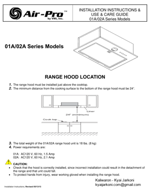
Installation Instructions, Revised 05/13/13 INSTALLATION INSTRUCTIONS & USE & CARE GUIDE 01A/02A Series Models 01A/02A Series Models RANGE HOOD LOCATION 1. The range hood must be installed just above the cooktop. 2. The minimum distance from the cooking surface to the bottom of the range hood must be 24fl. 3. The total weight of the 01A/02A range hood unit is 18 lbs. (8 kg) 4. Power requirements are: 01A: AC120 V, 60 Hz, 1.5 Amp 02A: AC120 V, 60 Hz, 2.1 Amp CAUTION: Check that the hood is correctly installed, since inco rrect installation could result in the detachment of the range and that unit could fall. To protect hands from injury, wear wo rking gloved when installing the range hood.
PAGE – 3 ============
Installation Instructions, Revised 05/13/13 SAFETY INSTRUCTIONS Before installation and operation, read these instructions carefully and use this product only in the manner described by the manufacturer in the operation manual. The instructions shown below are used to alert you to potential personal injury and properly damage hazards. There are three hazard classifications based on potentially dangerous situations. Obey all safety instructions t hat show these symbols to avoid possible injury, death and property damage. WARNING: WARNING indicates a potentially hazardous situation which, if not avoided, could result in death or serious injury. CAUTION: CAUTION indicates a potentially hazardous situation which, if not avoided, may result in minor or moderate injury. CAUTION: CAUTION indicates used without the safety alert symbol indicates a potentially hazardous situation which, if not avoided, may result in property damage. NOTE: The safety instructions are explained with the following pictographic symbols. means prohibition. It indicates actions, if any, that must not be done. means forcible execution. It indicates actions, if any, that must be done. WARNING 1. TO REDUCE THE RISK OF FIRE, ELECTRONIC SHOCK, OR INJURY TO PERSONS, OBSERVE THE FOLLOWING: Use this unit only in the manner indicated by the manufacturer. If you have questions, contact the manufacturer. Before servicing or cleaning the unit, switch power off at service panel and lock the service disconnecting means to prevent power from being switched on automatically. When the service disconnecting means cannot be locked, securely fasten a prominent warning device, such as a tag, to the service panel. 2. To reduce the risk of fire or electric shock, do not use this product with any solid-state speed control device. 3. TO REDUCE THE RISK OF FIRE, ELECTRIC SHOCK, OR INJURY TO PERSONS, OBSERVE THE FOLLOWING: Installation work and electrical wiring must be done by a qualified person(s) in accordance with all applicable codes and standards, including fire-rated construction. Sufficient air is needed for proper combustion and exhausting of gases through the flue (chimney) of fuel burning equipment manufacturer™s guidelines and safety standards such as those published by the National Fire Protection Association (NFPA), and The American Society for Heating, Refrigeration and Air Conditioning Engineers (ASHRAE), and the local code authorities. When cutting or drilling into wall or ceiling, do not damage electrical wiring and other hidden utilities. Ducted fan must always be vented to outdoors. 4. TO REDUCE THE RISK OF FIRE, USE ONLY METAL DUCTWORK. 5. This unit must be grounded. 6. Check that the hood is correctly installed, since incorrect installation could result in the range hood becoming detached and falling off. 7. Connect only to an AC120 Volt power source or the range hood could result in fire, electric shock, and damage. CAUTION 1. For general ventilating use only. Do not use to exhaust hazardous or explosive material and vapors. 2. To reduce the risk of fire and to properly exhaust air, be sure to duct air outside. Do not vent exhaust air into spaces within walls, ceilings or into attics, crawl spaces or garages. 3. Read specification label on this product for further information and requirements. 4. Use only for the purpose of kitchen ventilation. 5. Do not install this range hood in the bathroom or in other wet rooms since electrical shock and damage may result. 6. Fasten the filter and other parts securely. Incorrect attachment may result in personal injury or property damage. 7. Keep your hands and other objects away from the fan while it is in motion. The range hood may injure you or damage itself.
PAGE – 4 ============
Installation Instructions, Revised 05/13/13 PREPARATION WARNING: If the range hood is not installed properly, it could become detached and fall. Ensure that the metal duct does not touch other metal hous ing materials, otherwise fire or electric shock could result. 1. According to the conditions where the range hood is installed, determine whether it will discharge vertically or horizontally (7fl Round duct). For vertical or horizontal discharge, run duct work between the hood location and a roof cap or wall cap. For the best result in either direction, use a minimum number of transitions and elbows. Be sure to attach a roof cap or wall cap to avoid water leakage. 2. The range hood unit must be mounted to a liner which has t he dimensions. Install the liner securely after checking that the opening size of the liner is the same as the figure below. CAUTION: The liner should be installed tightly. If the liner in stallation is not correct, the range hood unit may become detached and fall off. WARNING Œ TO REDUCE THE RISK OF A RANGE TOP GREASE FIRE: a) Never leave surface units unattended at high settings. Boilovers cause smoking and greasy spillovers that may ignite. Heat oils slowly on low or medium settings. b) Always turn hood ON when cooking at high heat or when flam béing food (i.e. Crepes Suzette, Cherries Jubilee, Peppercorn Beef Flambé). c) Clean ventilating fans frequently. Grease should not be allowed to accumulate on fan or filter. d) Use proper pan size. Always use cookware ap propriate for the size of the surface element. CONNECTING TO THE VENT PIPE The 01A/02A series ventilation modules come with a metal start co llar. Attach the Start Collar to the duct with at least three equally spaced screws. Also apply duct tape, preferably the metal type. Some installations, (where the outside of this position of the duct is not accessible) will require the metal tape be applied on the inside of the duct. 7fl Round Duct (for Vertical Discharge) 7fl Round Duct (for Horizontal Discharge)
PAGE – 8 ============
Installation Instructions, Revised 05/13/13 CAUTION: The neutral wire (usually white) for the ventilator mu st connect to the same neutral wire that comes from the electrical panel to the liner. Factory Installed Variable-Speed Wiring Details Black 120 volt AC from electrical panel (usually black) White Neutral from electrical panel (white) Green Ground from electrical panel (usually green) Wiring Diagram 01A/02A Series Models Liner BLK WHT GRN House Electrical Panel Green White (N) 120V Black (L)
PAGE – 9 ============
Installation Instructions, Revised 05/13/13 WARRANTY Air-ProŽ Brand Ventilation Products What is Covered VMI Inc. warrants its Air-Pro Ž brand products to the original user, to be free of defects in materials and workmanship for three (3) years from the date of purchase. VMI Inc., at its option, will repair or replace the complete unit or any defective component without charge providing that, if requested, the product or defective component is promptly returned, prepai d to the address below. This warranty may be voided if any unauthorized service, alterati ons or repairs are made to the product. What is Not Covered Normal maintenance and service of any product that has been subject to misuse, negligence, accident or installation inconsistent with the recommended installation instructions Product used other than for normal in-home use or produ cts used outside of the United States and Canada. Damage to the product caused by accident, fire, flood or other acts of God. Service calls to educate the customer in the proper use an d care of the product, correct faulty installation, change fuses or reset breakers. VMI Inc. disclaims and excludes any liability for implied warrant ies or for incidental or consequential damages wherever permitted by law. There are no implied warranties of merchant ability or fitness for a particular use or purpose. This warranty gives you specific legal rights and you may also have other rights, which vary from state to state. For Service If you need service, contact Customer Service at the address or phone number below. Provide the model number, part identification and details of the problem. Proof of purchase must be provided. VMI Inc. P.O. Box 2765 Ł Redmond, WA 98073 Phone: 206-835-9880 Ł Fax: 206-835-9876 www.vmi-inc.net Rev. 04/13 VMI, Inc. P.O. Box 2765 Redmond, WA 98073 Toll Free: 1-888-547-9880 Phone: 206-835-9880 **** Fax: 206-835-9876
PAGE – 10 ============
Installation Instructions, Revised 05/13/13 Instructions d’Installation et Utilisation de Soins Guide 01A/02A Série Modèles 01A/02A Série Modèles GAMME EMPLACEMENT CAPOT 1. La plage du capot doit être installé juste au-dessus de la cuisinière. 2. La distance minimale de la surface de cuisson et le bas de la gamme du capot doit être de 24 “. 3. Le poids total du 01A/02A de la hotte est de 18 lbs (8 kg) 4. Exigences d’alimentation sont les suivantes: 01A: AC120 V, 60 Hz, 1.5 Amp 02A: AC120 V, 60 Hz, 2.1 Amp ATTENTION : Vérifier que le capot est correctement installé, ca r une mauvaise installation pourrait entraîner le détachement de la gamme et cette unité pourrait tomber. Pour protéger les mains contre les blessures, porte r les gants de travail lors de l’installation de la gamme le capot.
97 KB – 18 Pages